Evaluating the internal integrity of thick concrete structures—such as mass foundations, bridge piers, shear walls, and containment vessels—presents a unique set of non-destructive testing (NDT) challenges. Identifying subsurface flaws like honeycombing, consolidation voids, and delaminations before they compromise load-bearing capacity is vital. While Ground Penetrating Radar (GPR) is widely recognized as the premier tool for concrete scanning, its physical reliance on electromagnetic energy creates clear boundaries. Understanding where GPR hits its limit—and where Ultrasonic Pulse Echo (UPE) array technology steps in—is crucial for reliable structural diagnosis.
The Physics and Depth Limits of GPR in Concrete
GPR operates by emitting high-frequency electromagnetic (EM) pulses into a material and measuring the reflections caused by boundaries between materials with different dielectric constants (such as concrete, steel rebar, or air voids). Standard concrete scanning antennas operate at high frequencies (typically 1.6 GHz to 2.6 GHz) to provide sub-inch spatial resolution for rebar mapping and conduit detection.
However, GPR performance drops sharply when inspecting thick concrete for internal defects due to three fundamental physics limitations:
Electromagnetic Attenuation: High-frequency EM waves attenuate rapidly as they pass through concrete. Signal penetration depth is typically capped at 18 to 24 inches (45 to 60 cm). Moist concrete, high salt content, or heavy mineral additives accelerate this signal loss.
Rebar Shielding (Shadowing): Dense rebar mats act as a continuous metallic grid. Because steel reflects nearly 100% of the electromagnetic wave, upper rebar cages create a "radar shadow" that blocks signal transmission to deeper layers, masking features hidden beneath the steel.
Subtle Dielectric Contrasts: Honeycombing consists of pockets of poorly consolidated aggregate mixed with air voids and loose cement paste. Because it lacks a single, well-defined reflective boundary, honeycombing produces diffuse, low-amplitude reflections that GPR often fails to distinguish from background aggregate noise.
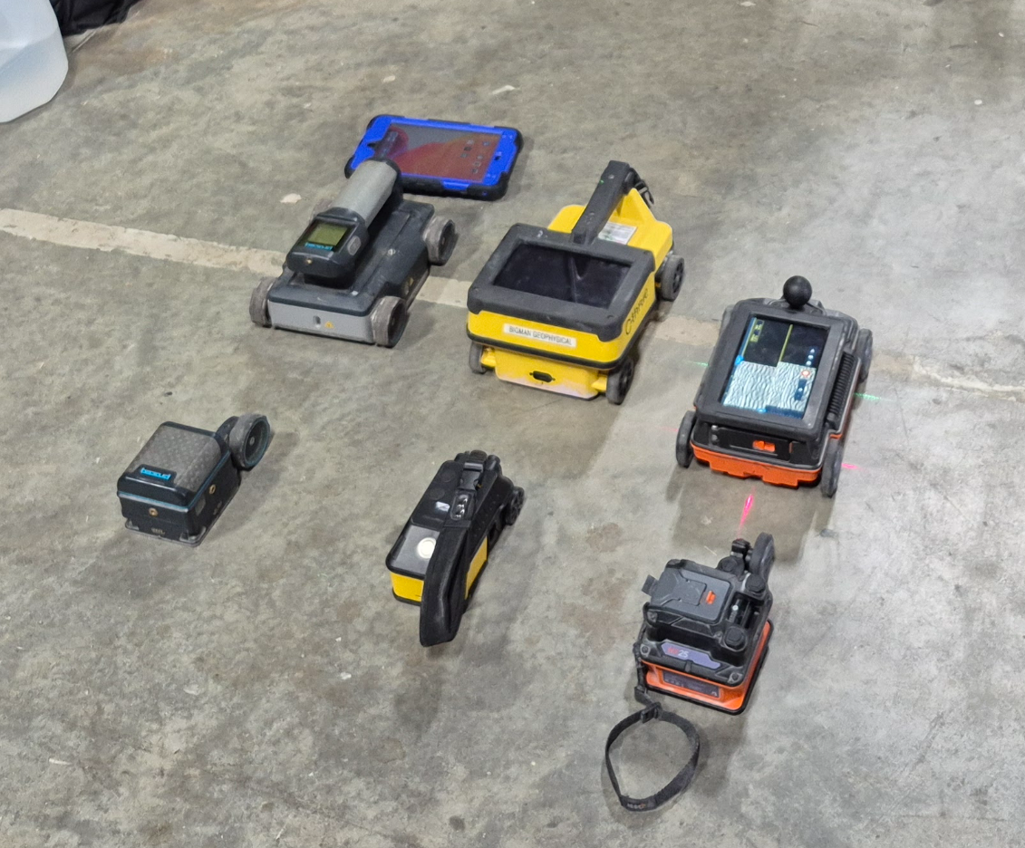
Where Ultrasonic Pulse Echo (UPE) Takes Over
To evaluate concrete beyond 2 feet deep or inspect regions behind dense rebar, NDT specialists rely on Ultrasonic Pulse Echo (UPE). Instead of electromagnetic waves, UPE systems emit low-frequency mechanical stress waves (sound waves, generally between 24 kHz and 100 kHz) into the concrete matrix using dry-contact transducer arrays.
Mechanical wave propagation fundamentally changes the inspection capabilities:
Extended Depth Penetration: Because low-frequency acoustic waves suffer significantly less signal loss in solid concrete, UPE arrays can reliably map structural thickness and detect anomalies at depths ranging from 3 feet up to 6+ feet (1 to 2+ meters).
High Sensitivity to Acoustic Impedance Discontinuities: Sound waves reflect strongly off changes in acoustic impedance (the product of material density and acoustic velocity). Air has near-zero acoustic impedance compared to solid concrete, causing internal voids, delaminations, and poorly consolidated honeycombed areas to reflect acoustic waves back to the receiving transducers with exceptionally high contrast.
Bypassing Rebar Cages: Low-frequency ultrasonic waves easily diffract around rebar grids rather than being blocked by them, allowing the acoustic signal to inspect the concrete matrix deep behind heavy reinforcement layers.
Advanced Synthetic Aperture Imaging: Modern UPE devices process multi-channel array signals using Synthetic Aperture Focusing Technique (SAFT) algorithms to generate real-time B-scans and tomographic cross-sections, transforming acoustic reflections into clear visual data.
Method Comparison: GPR vs. Ultrasonic Pulse Echo
| Feature / Metric | Ground Penetrating Radar (GPR) | Ultrasonic Pulse Echo (UPE) |
| Wave Type | Electromagnetic (Radio / Radar Waves) | Mechanical (Acoustic / Sound Waves) |
| Typical Frequency | High-frequency (1.6 GHz – 2.6 GHz) | Low-frequency (24 kHz – 100 kHz) |
| Effective Depth Limit | ~18 to 24 inches (45–60 cm) | ~3 to 6+ feet (1–2+ meters) |
| Rebar Shielding Impact | High (upper rebar masks lower features) | Minimal (sound waves pass around rebar) |
| Honeycombing & Voids | Low to Moderate (diffuse EM response) | High (strong acoustic reflection off air voids) |
| Primary Strength | Rapid rebar mapping & cover depth | Deep voids, element thickness, delaminations |
Implementing a Dual-Methodology Workflow
Rather than viewing GPR and UPE as competing systems, advanced structural diagnostics treat them as complementary components of a comprehensive NDT workflow:
Phase 1: Rapid GPR Scan — Deploy high-frequency GPR to swiftly map top-layer rebar spacing, cover depth, and embedded conduits across large surface areas.
Phase 2: Targeted UPE Imaging — Apply an ultrasonic array over areas with deep structural elements or suspected consolidation issues to verify total slab/pier thickness, locate deep voids behind rebar cages, and delineate honeycombed zones.
By combining the speed and near-surface resolution of GPR with the deep penetration and acoustic sensitivity of Ultrasonic Pulse Echo, field engineers ensure complete structural clarity across all depths. Bigman Geophysical recommondeds these technologies, and even published a featured project blog post to show the real-world application of those technologies together.
Watch this video breakdown on Limits of GPR for Structural Assessments from LearnGPR to see a head-to-head field comparison between GPR and Ultrasonic Pulse Echo when locating delaminations and measuring slab thickness.